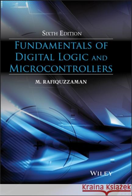
Microcontrollers 6e » książka


(netto: 590,24 VAT: 5%)
Najniższa cena z 30 dni: 615,94
ok. 30 dni roboczych.
Darmowa dostawa!
Updated to reflect the latest advances in the field, the Sixth Edition of Fundamentals of Digital Logic and Microcontrollers further enhances its reputation as the most accessible introduction to the basic principles and tools required in the design of digital systems.
- Features updates and revision to more than half of the material from the previous edition
- Offers an all-encompassing focus on the areas of computer design, digital logic, and digital systems, unlike other texts in the marketplace
- Written with clear and concise explanations of fundamental topics such as number system and Boolean algebra, and simplified examples and tutorials utilizing the PIC18F4321 microcontroller
- Covers an enhanced version of both combinational and sequential logic design, basics of computer organization, and microcontrollers
Glosariusz/słownik
PREFACE xiii
1: INTRODUCTION TO DIGITAL SYSTEMS 1
1.1 Explanation of Terms 2
1.2 Design Levels 6
1.3 Combinational and Sequential Circuits 7
1.4 Digital Integrated Circuits 7
1.4.1 Diodes 7
1.4.2 Transistors 8
1.4.3 MOS Transistors 14
1.5 Integrated Circuits (ICs) 18
1.6 CAD (Computer–Aided Design) 19
1.7 Evolution of the Microcontroller 20
1.8 Typical Microcontroller Applications 21
1.8.1 A Simple Microcontroller Application 22
1.8.2 Embedded Controllers 23
2: NUMBER SYSTEMS AND CODES 25
2.1 Number Systems 25
2.1.1 General Number Representation 25
2.1.2 Converting Numbers from One Base to Another 28
2.2 Unsigned and Signed Binary Numbers 30
2.3 Codes 34
2.3.1 Binary–Coded–Decimal Code (8421 Code) 34
2.3.2 Alphanumeric Codes 35
2.3.3 Excess–3 Code 36
2.3.4 Gray Code 37
2.3.5 Unicode 39
2.4 Fixed–Point and Floating–Point Representations 40
2.5 Arithmetic Operations 41
2.5.1 Binary Arithmetic 41
2.5.2 BCD Arithmetic 51
2.6 Error Correction and Detection 53
Questions and Problems 55
3: BOOLEAN ALGEBRA AND DIGITAL LOGIC GATES 59
3.1 Basic Logic Operations 59
3.1.1 NOT Operation 59
3.1.2 OR operation 60
3.1.3 AND operation 62
3.2 Other Logic Operations 64
3.2.1 NOR operation 64
3.2.2 NAND operation 64
3.2.3 Exclusive–OR operation (XOR) 65
3.2.4 Exclusive–NOR Operation (XNOR) 66
3.3 IEEE Symbols for Logic Gates 67
3.4 Positive and Negative Logic 68
3.5 Boolean Algebra 69
3.5.1 Boolean Identities 70
3.5.2 Simplification Using Boolean Identities 72
3.5.3 Consensus Theorem 74
3.5.4 Complement of a Boolean Function 75
3.6 Standard Representations 76
3.7 Karnaugh Maps 80
3.7.1 Two–Variable K–map 81
3.7.2 Three–Variable K–map 82
3.7.3 Four–Variable K–map 85
3.7.4 Prime Implicants 87
3.7.5 Expressing a Boolean function in Product–of–sums (POS) form using a K–map 89
3.7.6 Don t Care Conditions 91
3.7.7 Five–Variable K–map 95
3.8 Quine McCluskey Method 96
3.9 Implementation of Digital Circuits with NAND, NOR, and Exclusive–OR/Exclusive–NOR Gates 97
3.9.1 NAND Gate Implementation 98
3.9.2 NOR Gate Implementation 99
3.9.3 XOR / XNOR Implementations 102
Questions and Problems 106
4: COMBINATIONAL LOGIC 109
4.1 Basic Concepts 109
4.2 Analysis of a Combinational Logic Circuit 109
4.3 Design of a Combinational Circuit 110
4.4 Multiple–Output Combinational Circuits 112
4.5 Typical Combinational Circuits 114
4.5.1 Comparators 114
4.5.2 Decoders 118
4.5.3 Encoders 122
4.5.4 Multiplexers 127
4.5.5 Demultiplexers 129
4.5.6 Binary / BCD Adders and Binary Subtractors 129
4.6 IEEE Standard Symbols 136
4.7 Read–Only Memories (ROMs) 138
4.8 Programmable Logic Devices (PLDs) 140
4.9 Commercially Available Field Programmable Devices (FPDs) 144
4.10 HARDWARE DESCRIPTION LANGUAGE (HDL) 146
4.11 Verilog basics 148
4.11.1 Verilog keywords 148
4.11.2 A typical Verilog Segment 148
4.11.3 Verilog operators 151
4.11.4 Verilog Constants 152
4.11.5 Modeling logical conditions in a circuit 152
4.11.6 Verilog if–else and case–endcase structures 153
4.11.7 A typical Verilog Simulator 153
4.12 Verilog modeling examples for combinational circuits 155
4.12.1 Structural modeling 155
4.12.2 Dataflow modeling 161
4.12.3 Behavioral modeling 163
Questions and Problems 168
5: SEQUENTIAL LOGIC 173
5.1 Basic Concepts 173
5.2 Latches and Flip–Flops 173
5.2.1 SR Latch 174
5.2.2 Gated SR Latch 176
5.2.3 Gated D Latch 176
5.2.4 Edge–Triggered D Flip–Flop 177
5.2.5 JK Flip–Flop 180
5.2.6 T Flip–Flop 181
5.3 Flip–flop timing parameters for edge–triggered flip–flops 181
5.4 Preset and Clear Inputs 182
5.5 Summary of the gated SR latch and the Flip–Flops 182
5.6 Analysis of Synchronous Sequential Circuits 185
5.7 Types of Synchronous Sequential Circuits 188
5.8 Minimization of States 188
5.9 Design of Synchronous Sequential Circuits 190
5.10 Design of Counters 196
5.11 Examples of Synchronous Sequential Circuits 201
5.11.1 Registers 201
5.11.2 Modulo–n Counters 203
5.11.3 Random–Access Memory (RAM) 206
5.12 Algorithmic State Machines (ASM) Chart 207
5.13 Asynchronous Sequential Circuits 214
5.14 Verilog description of typical synchronous sequential circuits 217
Questions and Problems 235
6: CPU, MEMORY, AND I/O 243
6.1 Design of the CPU 243
6.1.1 Register Design 244
6.1.2 Arithmetic Logic Unit (ALU) 244
6.1.3 ALU Design 255
6.1.4 Control Unit Design 257
6.2 Memory Organization 280
6.2.1 Types of Main memory 283
6.2.2 READ and WRITE Timing Diagrams 285
6.2.3 Main Memory Organization 287
6.3 Input/Output (I/O) 290
6.3.1 Simple I/O Devices 292
6.3.2 Programmed I/O 293
6.3.3 Interrupt I/O 295
6.4 CPU design using Verilog 296
Questions and Problems 309
7: MICROCONTROLLER BASICS 317
7.1 Basic Blocks of a Microcontroller 317
7.1.1 System Bus 318
7.1.2 Clock Signals 319
7.2 Microcontroller Architectures 320
7.3 Basic Concept of Pipelining 321
7.4 RISC vs. CISC 323
7.5 Functional Representation of a Typical RISC Microcontroller The PIC18F4321 324
7.6 Basics of Programming Languages 324
7.6.1 Machine Language 326
7.6.2 Assembly Language 327
7.6.3 High Level Language 327
7.7 Choosing a Programming Language 328
7.8 Introduction to C Language 329
7.8.1 Data Types 332
7.8.2 Bit Manipulation Operators 333
7.8.3 Control Structures 334
7.8.4 The switch Construct 338
7.8.5 The while Construct 338
7.8.6 The for Construct 340
7.8.7 The do while Construct 341
7.8.8 Structures and Unions 341
7.8.9 Functions in C 342
7.8.10 Macros 343
Questions and Problems 344
8: PIC18F HARDWARE AND INTERFACING USING C: PART 1 345
8.1 PIC18F Pins and Signals 345
8.1.1 Clock 346
8.1.2 PIC18F Reset 350
8.1.3 A Simplified Setup for the PIC18F4321 350
8.2 PIC18F4321 programmed I/O using C 351
8.2.1 PIC 18F4321 I/O ports 351
8.2.2 Interfacing LEDs (Light Emitting Diodes) and Seven segment Displays 354
8.2.3 Microchip MPLAB C18 compiler and the PICkit3 interface 355
8.2.4 Configuration commands 356
8.3 PIC18F Interrupts 359
8.3.1 PIC18F Interrupt Types 359
8.3.2 PIC18F External Interrupts in Default Mode 359
8.3.3 Interrupt Registers and Priorities 361
8.3.4 Setting the Triggering Levels of INTn Pin Interrupts 362
8.3.5 Programming the PIC18 interrupts using C 363
Questions and Problems 369
9: PIC18F HARDWARE AND INTERFACING USING C: PART 2 373
9.1 PIC18F Timers 373
9.1.1 Timer0 375
9.1.2 Timer1 378
9.1.3 Timer2 382
9.1.4 Timer3 384
9.2 PIC18F Interface to an LCD (Liquid Crystal Display) 390
9.3 Analog Interface 394
9.3.1 On–chip A/D Converter 395
9.3.2 Interfacing an External D/A (Digital–to–Analog) Converter to the PIC18F4321 403
9.4 Serial Interface 405
9.4.1 Synchronous Serial Data Transmission 405
9.4.2 Asynchronous Serial Data Transmission 405
9.4.3 PIC18F Serial I/O 406
9.5 PIC18F4321 Capture/Compare/PWM (CCP) Modules 413
9.5.1 CCP Registers 413
9.5.2 CCP Modules and Associated Timers 413
9.5.3 PIC18F4321 Capture Mode 413
9.5.4 PIC18F4321 Compare Mode 416
9.5.5 PIC18F4321 PWM (Pulse Width Modulation) Mode 417
9.6 DC Motor Control 419
Questions and Problems 425
APPENDIX A: ANSWERS TO SELECTED PROBLEMS 429
APPENDIX B: GLOSSARY 439
APPENDIX C: TUTORIAL FOR COMPILING AND DEBUGGING A C–PROGRAM USING THE MPLAB 451
APPENDIX D: INTERFACING THE PIC18F4321 TO A PERSONAL COMPUTER OR A LAPTOP USING PICkit 3 479
D.1 INITIAL HARDWARE SETUP FOR THE PIC18F4321 479
D.2 CONNECTING THE PERSONAL COMPUTER (PC) OR THE LAPTOP TO THE PIC18F4321 VIA PICkit3 480
D.3 PROGRAMMING THE PIC18F4321 FROM A PERSONAL COMPUTER OR A LAPTOP USING THE PICkit3 482
BIBLIOGRAPHY 485
CREDITS 487
INDEX 489
M. RAFIQUZZAMAN is Professor of Electrical and Computer Engineering at California State Polytechnic University, Pomona. Dr. Rafiquzzaman is the founder of Rafi Systems, Inc., a manufacturer of biomedical devices and a computer systems consulting firm in California.
Updated to reflect the latest advances in the field, the Sixth Edition of Fundamentals of Digital Logic and Microcontrollers further enhances its reputation as the most accessible introduction to the basic principles and tools required in the design of digital systems.
Features updates and revision to more than half of the material from the previous edition
Offers an all–encompassing focus on the areas of computer design, digital logic, and digital systems, unlike other texts in the marketplace
Written with clear and concise explanations of fundamental topics such as number system and Boolean algebra, and simplified examples and tutorials utilizing the PIC18F4321 microcontroller
Covers an enhanced version of both combinational and sequential logic design, basics of computer organization, and microcontrollers
1997-2026 DolnySlask.com Agencja Internetowa
KrainaKsiazek.PL - Księgarnia Internetowa


