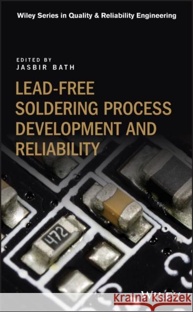
Lead-Free Soldering Process Development and Reliability » książka


Lead-Free Soldering Process Development and Reliability
ISBN-13: 9781119482031 / Angielski / Twarda / 2020 / 512 str.
Lead-Free Soldering Process Development and Reliability
ISBN-13: 9781119482031 / Angielski / Twarda / 2020 / 512 str.
(netto: 533,86 VAT: 5%)
Najniższa cena z 30 dni: 554,83
ok. 30 dni roboczych.
Darmowa dostawa!
List of Contributors xixIntroduction xxi1 Lead-Free Surface Mount Technology 1Jennifer Nguyen and Jasbir Bath1.1 Introduction 11.2 Lead-Free Solder Paste Alloys 11.3 Solder Paste Printing 21.3.1 Introduction 21.3.2 Key Paste Printing Elements 21.4 Component Placement 51.4.1 Introduction 51.4.2 Key Placement Parameters 51.4.2.1 Nozzle 61.4.2.2 Vision System 61.4.2.3 PCB Support 61.4.2.4 Component Size, Packaging, and Feeder Capacity 61.4.2.5 Feeder Capacity 61.5 Reflow Process 71.5.1 Introduction 71.5.2 Key Parameters 71.5.2.1 Preheat 71.5.2.2 Soak 81.5.2.3 Reflow 81.5.2.4 Cooling 91.5.2.5 Reflow Atmosphere 91.6 Vacuum Soldering 91.7 Paste in Hole 101.8 Robotic Soldering 111.9 Advanced Technologies 121.9.1 Flip Chip 121.9.2 Package on Package 121.10 Inspection 131.10.1 Solder Paste Inspection (SPI) 131.10.2 Solder Joint Inspection 141.10.2.1 Automated Optical Inspection (AOI) 141.10.2.2 X-ray Inspection 151.11 Conclusions 16References 172 Wave/Selective Soldering 19Gerjan Diepstraten2.1 Introduction 192.2 Flux 192.2.1 The Function of a Flux 192.2.2 Flux Contents 202.3 Amount of Flux Application on a Board 202.4 Flux Handling 212.5 Flux Application 212.5.1 Methods to Apply Flux (Wave Soldering) 212.5.2 Methods to Apply Flux (Selective Soldering) 232.6 Preheat 242.6.1 Preheat Process-Heating Methods 242.6.2 Preheat Temperatures 272.6.3 Preheat Time 282.6.4 Controlling Preheat Temperatures 282.6.5 BoardWarpage Compensation (Selective Soldering) 292.7 Selective Soldering 292.7.1 Different Selective Soldering Point to Point Nozzles (Selective Soldering) 292.7.2 Solder Temperatures (Selective Soldering) 302.7.3 Dip/Contact Times (Selective Soldering) 312.7.4 Drag Conditions (Selective Soldering) 312.7.5 Nitrogen Environment (Selective Soldering) 312.7.6 Wave Height Controls (Selective Soldering) 322.7.7 De-Bridging Tools (Selective Soldering) 322.7.8 Solder Pot (Selective Soldering) 332.7.9 Topside Heating during Soldering (Selective Soldering) 342.7.10 Selective Soldering Dip Process with Nozzle Plates (Selective Soldering) 342.7.11 Solder Temperatures for Multi-Wave Dip Soldering (Selective Soldering) 352.7.12 Nitrogen Environment (Selective Soldering) 352.7.13 Wave Height Control (Selective Soldering) 362.7.14 Dip Time - Contact Time with Solder (Selective Soldering) 362.7.15 Solder Flow Acceleration and Deceleration (Selective Soldering) 372.7.16 De-Bridging Tools (Selective Soldering) 372.7.17 Pallets (Selective Soldering) 382.7.18 Conveyor (Selective Soldering) 382.8 Wave Soldering 392.8.1 Wave Formers (Wave Soldering) 392.8.2 Pallets (Wave Soldering) 402.8.3 Nitrogen Environment (Wave Soldering) 402.8.4 Process Control (Wave Soldering) 412.8.5 Conveyor (Wave Soldering) 412.9 Conclusions 42References 423 Lead-Free Rework 43Jasbir Bath3.1 Introduction 433.2 Hand Soldering Rework for SMT and PTH Components 433.2.1 Alloy and Flux Choices 433.2.1.1 Alloys 433.2.1.2 Flux 443.2.2 Soldering Iron Tip Life 443.2.3 Hand Soldering Temperatures and Times 473.3 BGA/CSP Rework 503.3.1 Alloy and Flux Choices 503.3.1.1 Alloys 503.3.1.2 Flux 503.3.2 BGA/CSP Rework Soldering Temperatures and Times 503.3.3 Component Temperatures in Relation to IPC/JEDEC J-STD-020 and Component/BoardWarpage Standards 523.3.3.1 IPC/JEDEC J-STD-020 Standard 523.3.3.2 ComponentWarpage Standards 523.3.3.3 BoardWarpage Standards 523.3.4 Equipment Updates for Lead-Free BGA/CSP Rework 533.3.5 Adjacent Component Temperatures 533.4 Non-standard Component Rework (Including BTC/QFN) 543.4.1 Alloy and Flux Choices 543.4.1.1 Alloys 543.4.1.2 Flux 543.4.2 Soldering Temperatures and Times 543.4.3 Non-standard Component Temperatures in Relation to IPC JEDEC J-STD-020 Standard and ComponentWarpage Standards 553.4.4 Equipment and Tooling Updates for Lead-Free Non-standard Component Rework 553.4.5 Adjacent Component Temperatures 563.4.6 Non-standard Component Rework Solder Joint Reliability 563.5 PTH (Pin-Through-Hole)Wave Rework 563.5.1 Alloy and Flux Choices 563.5.1.1 Alloys 563.5.1.2 Flux 573.5.2 Soldering Temperatures and Times 573.5.3 Component Temperatures in Relation to Industry and Board Standards During PTH Rework 673.5.3.1 Component Temperature Rating Standards 673.5.3.2 Bare Board Testing Standards and Methods for PTH Rework 673.5.4 Equipment Updates for PTH Component Rework 683.5.5 Adjacent Component Temperatures During PTH Rework 683.5.6 PTH Component Rework Solder Joint Reliability 683.5.6.1 Copper Dissolution 683.5.6.2 Holefill 693.6 Conclusions 69References 704 Solder Paste and Flux Technology 73Shantanu Joshi and Peter Borgesen4.1 Introduction 734.2 Solder Paste 754.2.1 Water-Soluble Solder Paste 754.2.2 No-Clean Solder Paste 764.3 Flux Technology 774.3.1 Halide-Free and Halide-Containing 774.4 Composition of Solder Paste 794.4.1 Alloy 794.4.2 Flux 824.4.3 Solder Powder Type 834.4.3.1 Oxide Layer 844.5 Characteristics of a Solder Paste 844.5.1 Printing 844.5.1.1 Printing Parameters 854.5.2 Reflow 864.5.2.1 Wetting/Spreadability of Lead-Free Solder Paste 864.5.2.2 Bridging 864.5.2.3 Micro Solder Balls 864.5.2.4 Voiding 864.5.2.5 Head-on-Pillow Component Soldering Defect 884.5.2.6 Non-Wet Open 904.5.2.7 Tombstoning 904.5.3 In-Circuit Test (ICT) Probe Testability 904.5.4 Flux Reliability Issues 914.6 Conclusions 92References 925 Low Temperature Lead-Free Alloys and Solder Pastes 95Raiyo Aspandiar, Nilesh Badwe, and Kevin Byrd5.1 Introduction 955.1.1 Definition of Low Temperature Solders 955.1.2 Benefits of Low Temperature Soldering 975.1.2.1 Reduced Manufacturing Cost 985.1.2.2 Power Use Savings 985.1.2.3 Environmental Benefits 995.1.2.4 Manufacturing Yield Improvements 1005.1.3 Drawbacks 1035.1.3.1 Brittleness 1035.1.4 Other Low Temperature Metallurgical Systems 1035.2 Development of Robust Bismuth-Based Low Temperature Solder Alloys 1055.2.1 Bismuth-Tin (Bi-Sn) Phase Diagram 1055.2.2 Mechanical Properties 1075.2.3 Physical Properties 1085.2.4 Alloy Development Progress 1085.2.5 Fluxes for Low Temperature Solders 1095.3 SMT Process Characterization of Sn-Bi Based Solder Pastes 1115.3.1 Printability 1115.3.2 Reflow Profiles 1125.3.3 Rework 1135.4 Polymeric Reinforcement of Sn-Bi Based Low Temperature Alloys 1145.4.1 Current Polymeric Reinforcement Strategies 1145.4.2 Joint Reinforced Pastes (JRP) 1185.4.3 Polymeric Reinforcement Summary 1285.5 Mixed SnAgCu-BiSn BGA Solder Joints 1285.5.1 Formation Mechanism 1285.5.2 Microstructural Features and Key Characteristics 1335.5.3 Soldering Process Optimization 1345.5.4 Possible Defects 1355.6 Solder Joint Reliability 1405.7 Conclusions 1455.8 Future Development and Trends 146References 1496 High Temperature Lead-Free Bonding Materials - The Need, the Potential Candidates and the Challenges 155Hongwen Zhang and Ning-Cheng Lee6.1 Introduction 1556.2 Solder Materials 1596.2.1 Gold-Based Solders 1596.2.2 Bismuth-Rich Solders 1606.2.2.1 Design of Bismuth-Rich Solders 1606.2.2.2 Mechanical Behavior of BiAgX 1636.2.2.3 Microstructure and Microstructural Evolution of BiAgX Joint 1676.2.3 Tin-Antimony (Sn-Sb) High Temperature Solders 1746.2.4 Zinc-Aluminum Solders 1766.3 Silver (Ag)-Sintering Materials 1786.4 Transient Liquid Phase Bonding Materials/Technique 1816.5 Summary 182Acknowledgment 185References 1857 Lead (Pb)-Free Solders for High Reliability and High-Performance Applications 191Richard J. Coyle7.1 Evolution of Commercial Lead (Pb)-Free Solder Alloys 1917.1.1 First Generation Commercial Pb-Free Solders 1917.1.2 Second Generation Commercial Pb-Free Solders 1927.1.3 Third Generation Commercial Pb-Free Solders 1967.2 Third Generation Alloy Research and Development 1967.2.1 Limitations of Sn-Ag-Cu Solder Alloys 1967.2.2 Emergence of Commercial Third Generation Alloys 2027.2.2.1 The Genesis of 3rd Generation Alloy Development 2027.2.2.2 An Expanding Class of 3rd Generation Alloys 2027.2.3 Metallurgical Considerations 2037.2.3.1 Antimony (Sb) Additions to Tin (Sn) 2067.2.3.2 Indium (In) Additions to Tin (Sn) 2077.2.3.3 Bismuth (Bi) Additions to Tin (Sn) 2097.3 Reliability Testing Third Generation Commercial Pb-Free Solders 2107.3.1 Thermal Fatigue Evaluations 2107.3.2 iNEMI/HDPUG Third Generation Alloy Pb-Free Thermal Fatigue Project 2137.3.3 Microstructure and Reliability of Third Generation Alloys 2197.4 Reliability Gaps and Suggestions for AdditionalWork 2237.4.1 Root Cause of Interfacial Fractures 2237.4.2 Effect of Component Attributes on Thermal Fatigue 2247.4.3 Effect of Surface Finish on Thermal Fatigue 2247.4.4 Thermomechanical Test Parameters and Test Outcomes 2257.4.4.1 Thermal Cycling Dwell Time 2257.4.4.2 Preconditioning (Isothermal Aging) 2257.4.4.3 Thermal Cycling of Mixed Metallurgy BGA Assemblies 2267.4.4.4 Thermal Shock or Aggressive Thermal Cycling 2267.4.5 Reliability Under Mechanical Loading: Drop/Shock, and Vibration 2277.4.6 Solder Alloy Microstructure and Reliability 2307.4.7 Summary of Suggestions for Additional Investigation 2317.5 Conclusions 232Acknowledgments 234References 2348 Lead-Free Printed Wiring Board Surface Finishes 249Rick Nichols8.1 Introduction: Why a Surface Finish is Needed 2498.2 Surface Finishes in the Market 2508.3 Application Perspective 2558.4 A Description of Final Finishes 2618.4.1 Hot Air Solder Leveling (HASL) 2638.4.1.1 Process Complexity 2638.4.1.2 Process Description 2658.4.1.3 Issues and Remedies 2678.4.1.4 Summary 2678.4.2 High Temperature OSP 2678.4.2.1 Process Complexity 2678.4.2.2 Process Description 2698.4.2.3 Issues and Remedies 2708.4.2.4 Summary 2708.4.3 Immersion Tin 2718.4.3.1 Process Complexity 2718.4.3.2 Process Description 2738.4.3.3 Issues and Remedies 2758.4.3.4 Summary 2768.4.4 Immersion Silver 2768.4.4.1 Process Complexity 2778.4.4.2 Process Description 2798.4.4.3 Issues and Remedies 2808.4.4.4 Summary 2818.4.5 Electroless Nickel Immersion Gold (ENIG) 2818.4.5.1 Process Complexity 2818.4.5.2 Process Description 2838.4.5.3 Issues and Remedies 2858.4.5.4 Summary 2868.4.6 Electroless Nickel/Electroless Palladium/Immersion Gold (ENEPIG) 2878.4.6.1 Process Complexity 2878.4.6.2 Process Description 2898.4.6.3 Issues and Remedies 2908.4.6.4 Summary 2918.4.7 Electroless Nickel Autocatalytic Gold (ENAG) 2918.4.7.1 Process Complexity 2928.4.7.2 Process Description 2938.4.7.3 Issues and Remedies 2958.4.7.4 Summary 2958.4.8 Electroless Palladium Autocatalytic Gold (EPAG) 2958.4.8.1 Process Complexity 2958.4.8.2 Process Description 2978.4.8.3 Issues and Remedies 2988.4.8.4 Summary 2998.4.9 Electrolytic Nickel Electrolytic Gold 2998.4.9.1 Process Complexity 2998.4.9.2 Process Description 3018.4.9.3 Issues and Remedies 3018.4.9.4 Summary 3028.5 Conclusions 303References 3049 PCB Laminates (Including High Speed Requirements) 307Karl Sauter and Silvio Bertling9.1 Introduction 3079.2 Manufacturing Background 3079.3 PCB Fabrication Design and Laminate Manufacturing Factors Affecting Yield and Reliability 3089.3.1 High Frequency Loss 3089.3.2 Mixed Dielectric 3089.3.3 Back-Drilling 3099.3.4 Aspect Ratio 3099.3.5 PCB Fabrication 3099.3.6 Press Lamination 3109.3.7 Moisture Content 3109.3.8 Laminate Material 3119.4 Assembly Factors Affecting Yields and Long-Term Reliability for Laminate Materials 3119.4.1 Reflow Temperature 3119.4.2 Assembly Components 3129.4.3 Thermal Stress 3129.5 Copper Foil Trends (by Silvio Bertling) 3129.6 High Frequency/High Speed and Other Trends Affecting Laminate Materials 3169.6.1 High Speed Standards 3169.6.2 Adhesion Treatment (Prior to Press Lamination) 3179.6.3 Laminate Material Filler Content 3179.6.4 GlassWeave Effect 3179.6.5 Halogen-Free 3189.7 Conclusions 318References 31910 Underfills and Encapsulants Used in Lead-Free Electronic Assembly 321Brian J. Toleno10.1 Introduction 32110.2 Rheology 32210.2.1 Rheological Response and Behavior 32310.2.1.1 Thixotropy 32510.2.2 Measuring Rheology 32710.2.2.1 Spindle Type Viscometry 32710.2.2.2 Cone and Plate Rheometry 32810.3 Curing of Adhesive Systems 33010.3.1 Thermal Cure 33010.3.2 Ultraviolet (UV) Light Curing 33510.3.3 Moisture Cure 33810.4 Glass Transition Temperature 33910.5 Coefficient of Thermal Expansion (CTE) 34110.6 Young's Modulus (E) 34310.7 Applications 34410.7.1 Underfills 34410.7.1.1 Capillary Underfill 34510.7.1.2 Fluxing (No-Flow) Underfill 34810.7.1.3 Removable/Reworkable Underfill 34910.7.1.4 Staking or Corner Bond Underfill 34910.7.2 Encapsulant Materials 35010.7.2.1 Glob Top 35110.7.2.2 Component Encapsulation 35110.7.2.3 Application 35310.7.2.4 Low-Pressure Molding 35510.8 Conclusions 355References 35511 Thermal Cycling and General Reliability Considerations 359Maxim Serebreni11.1 Introduction to Thermal Cycling of Electronics 35911.1.1 Influence of Solder Alloy Composition and Microstructure on Thermal Cycling Reliability 36211.2 Influence of Package Type and Thermal Cycling Profile 36311.2.1 Influence of Board and Pad Design 36611.3 Fatigue Life Prediction Models 37111.3.1 Empirical Models and Acceleration Factors 37111.3.2 Semi-empirical Models 37211.3.3 Finite Element Analysis (FEA) Based Fatigue Life Predictions 37311.4 Conclusions 376References 37712 Intermetallic Compounds 381Alyssa Yaeger, Travis Dale, Elizabeth McClamrock, Ganesh Subbarayan, and Carol Handwerker12.1 Introduction 38112.1.1 Solders 38212.1.2 Interaction with Substrates 38212.2 Setting the Stage 38412.2.1 Mechanical and Thermomechanical Response of Solder Joints 38612.3 Common Lead-Free Solder Alloy Systems 39212.3.1 Solder Joints Formed Between Sn-Cu, Sn-Ag, and Sn-Ag-Cu Solder Alloys and Copper Surface Finishes 39612.3.1.1 Sn-Cu Solder on Copper 39612.3.1.2 Sn-Ag and Sn-Ag-Cu Solder Alloys on Copper 39912.3.2 Solder Joints Formed Between Sn-Cu, Sn-Ag, and Sn-Ag-Cu Alloys and Nickel Surface Finishes 40812.3.2.1 Ni-Sn 40812.3.2.2 Sn-Ag Solder Alloys on Nickel 41112.3.2.3 Spalling 41512.3.2.4 Effects of Phosphorus Concentration in ENIG on Solder Joint Reliability 41612.3.3 Au-Sn 41712.4 High Lead - Exemption 42212.5 Conclusions 423References 42313 Conformal Coatings 429Jason Keeping13.1 Introduction 42913.2 Environmental, Health, and Safety (EHS) Requirements 43013.3 Overview of Types of Conformal Coatings 43013.3.1 Types of Conformal Coatings 43113.3.1.1 Acrylic Resins (Type AR) 43213.3.1.2 Urethane Resins (Type UR) 43313.3.1.3 Epoxy Resins (Type ER) 43313.3.1.4 Silicone Resins (Type SR) 43513.3.1.5 Para-xylylene (Type XY) 43613.3.1.6 Synthetic Rubber (Type SC) 43713.3.1.7 Ultra-Thin (Type UT) 43813.4 Preparatory Steps Necessary to Ensure a Successful Coating Process 44013.4.1 Assembly Cleaning 44013.4.2 Assembly Masking 44013.4.3 Priming and Other Surface Treatments 44113.4.3.1 Measuring Surface Energy 44113.4.3.2 Water Drop Contact Angle 44713.4.4 Bake-Out 44813.5 Various Methods of Applying Conformal Coating 44913.5.1 Manual Coating 44913.5.2 Dip 44913.5.3 Hand Spray 45013.5.4 Automatic Spray 45113.5.5 Selective Coating 45113.5.6 Vapor Deposition 45113.6 Aspects for Cure, Inspection, and Demasking 45313.6.1 Cure 45313.6.1.1 Solvent Evaporation 45313.6.1.2 Room Temperature Vulcanization (RTV) 45413.6.1.3 Heat Cure 45413.6.1.4 UV Cure 45413.6.1.5 Catalyzed 45413.6.2 UV Inspection 45513.6.3 Demasking 45513.7 Repair and Rework Processes 45613.7.1 Chemical 45613.7.2 Thermal 45613.7.3 Mechanical 45713.7.4 Abrasion (Micro-Abrasion) 45713.7.5 Plasma Etch 45713.8 Design Guidance on When and Where Conformal Coating is Required, and Which Physical Characteristics and Properties are Important to Consider 45713.8.1 Is Conformal Coating Required? 45813.8.1.1 Why Use It? 45813.8.1.2 Why Not Use Conformal Coating? 45913.8.2 Desirable Material Properties 45913.8.3 Areas to Mask 46113.9 Long-Term Reliability and Testing 46213.10 Conclusions 46213.11 Future Work 463References 463Index 467
JASBIR BATH, is the owner of Bath Consultancy LLC which provides consulting and training services in the electronics manufacturing industry. He was the Corporate Lead Engineer with Solectron Corporation/ Flex for ten years with a role involving tin-lead and lead-free solder process development. Previously he was a Technical Officer at ITRI (International Tin Research Institute/ Tin Technology) Ltd in the U.K.
1997-2026 DolnySlask.com Agencja Internetowa
KrainaKsiazek.PL - Księgarnia Internetowa


