Handbook of Filter Synthesis » książka


Handbook of Filter Synthesis
ISBN-13: 9780471749424 / Angielski / Miękka / 2005 / 592 str.
Handbook of Filter Synthesis
ISBN-13: 9780471749424 / Angielski / Miękka / 2005 / 592 str.
(netto: 499,56 VAT: 5%)
Najniższa cena z 30 dni: 519,18
ok. 30 dni roboczych.
Darmowa dostawa!
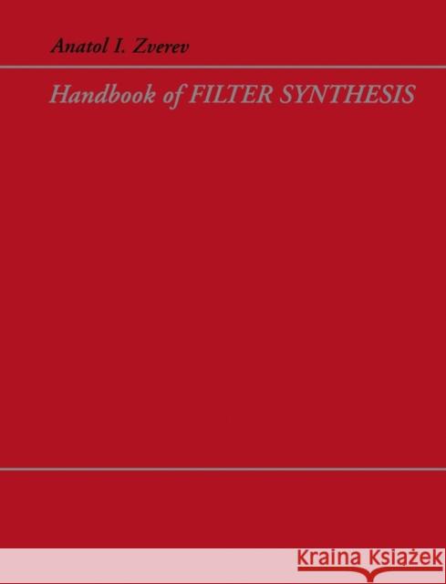
Handbook of Filter Synthesis, originally published in 1967 is the classic reference for continuous time filter design. The plots of filter behaviour for different designs, such as ripple and group delay, make this book invaluable. The discussion of how to synthesize a bandpass, bandpass, or bandstop filter from a lowpass prototype is also very useful.
Wydanie ilustrowane
CHAPTER 1. FILTERS IN ELECTRONICS.
1.1 Types of Filters.
1.2 Filter Applications.
1.3 All–Pass Filters.
1.4 Properties of Lattice Filters.
1.5 Filter Building Blocks.
1.6 Higher Order Filters.
1.7 Coil–Saving Bandpass Filters.
1.8 Frequency Range of Applications.
1.9 Physical Elements of the Filter.
1.10 Active Bandpass Filters.
1.11 RC Passive and Active Filters.
1.12 Microwave Filters.
1.13 Parametric Filters.
CHAPTER 2. THEORY OF EFFECTIVE PARAMETERS.
2.1 Power Balance.
2.2 Types of General Network Equations.
2.3 Effective Attenuation.
2.4 Reflective (Echo) Attenuation.
2.5 Transmission Function as a Function of Frequency Parameter, s.
2.6 Polynomials of Transmission and Filtering Functions.
2.7 Filter Networks.
2.8 Voltage and Current Sources.
2.9 The Function D (s) As An Approximation Function.
2.10 Example of Transmission Function Approximation.
2.11 Simplest Polynomial Filters in Algebraic Form.
2.12 Introduction to Image=Parameter Theory.
2.13 Bridge Networks.
2.14 Examples of Realization in the Bridge Form.
2.15 Hurwitz Polynomial.
2.16 The Smallest Realizabel Networks,
2.17 Fourth–Order Networks.
2.18 Fifth–Order Networks.
CHAPTER 3. FILTER CHARACTERISTICS IN THE FREQUENCY DOMAIN.
3.1 Amplitude Responses.
3.2 Phase–and Group–Delay Responses.
3.3 Group Delay of an Idealized Filter.
3.4 Group Delay–Attenuation Relationship.
3.5 The Chebyshev Family of Response Characteristics.
3.6 Gaussian Family of Response Characteristics.
3.7 A Filter with Transitional Magnitude Characteristics.
3.8 Legendre Filters.
3.9 Minimum–Loss Characteristics.
3.10 Synchronously Tuned Filters.
3.11 Arithmetically Symmetrical Bandpass Filters.
3.12 Attenuation Characteristics of Image Parameter Filters.
3.13 Other Types of Filter Characteristics.
3.14 Plots of the Attenuation and Group Delay Characteristics.
CHAPTER 4. ELLIPTIC FUNCTION AND ELEMENTS OF REALIZATION.
4.1 Double Periodic Elliptic Functions.
4.2 Mapping of s–Plane into u–Plane.
4.3 First Basic Transformation of Elliptic Functions.
4.4 Filtering Function in z–Plane.
4.5 Graphical Representation of Parameters.
4.6 Characteristic Value of D(s).
4.7 An Example of Filter Design.
4.8 Consideration of Losses.
4.9 Introduction of Losses by Frequency Transformation.
4.10 Highpass Filters with Losses.
4.11 Transmission Functions with Losses.
4.12 Conclusions on Consideration of Losses.
4.13 Realization Process.
4.14 Bandpass Filter with a Minimum Number of Inductors.
4.15 The Elements of a Coil–Saving Network.
4.16 Consideration of Losses in Zig–Zag Filters.
4.17 Realization Procedure.
4.18 Numerical Example of Realization.
4.19 Full and Partial Removal for a Fifth–Order Filter.
CHAPTER 5. THE CATALOG OF NORMALIZED LOWPASS FILTERS.
5.1 Introduction to the Catalog.
5.2 Real Part of the Driving Point Impedance.
5.3 Lowpass Filter Design.
5.4 Design of Highpass Filters.
5.5 Design of LC Bandpass Filters.
5.6 Design of Narrowband Crystal Filters.
5.7 Design of Bandstop Filters.
5.8 Catalog of Normalized Lowpass Models.
CHAPTER 6. DESIGN TECHNIQUES FOR POLYNOMIAL FILTERS.
6.1 Introduction to Tables of Normalized Element Values.
6.2 Lowpass Design Examples.
6.3 Bandpass Filter Design.
6.4 Concept of Coupling.
6.5 Coupled Resonators.
6.6 Second–Order Bandpass Filter.
6.7 Design with Tables of Predistorted k and q Parameters.
6.8 Design Examples using Tables of k and q Values.
6.9 Tables of Lowpass Element Values.
6.10 Tables of 3–dB Down k and q Values.
CHAPTER 7. FILTER CHARACTERISTICS IN THE TIME DOMAIN.
7.1 Introduction to Transient Characteristics.
7.2 Time and Frequency Domains.
7.3 Information Contained in the Impulse Response.
7.4 Step Response.
7.5 Impulse Response of an Ideal Gaussian Filter.
7.6 Residue Determination.
7.7 Numerical Example.
7.8 Practical Steps on the Inverse Transformation.
7.9 Inverse Transform of Rational Spectral Functions.
7.10 Numerical Example.
7.11 Estimation Theory.
7.12 Transient Response in Highpass and Bandpass Filters.
7.13 The Exact Calculation of Transient Phenomena for Highpass Systems.
7.14 Estimate of Transient Responses in Narrowband Filters.
7.15 The Exact Transient Calculation in Narrowband Systems.
7.16 Group Delay Versus Transient Response.
7.17 Computer Determination of Filter Impulse Response.
7.18 Transient Response Curves.
CHAPTER 8. CRYSTAL FILTERS.
8.1 Introduction.
8.2 Crystal Structure.
8.3 Theory of Piezoelectricity.
8.4 Properties of Piezoelectric Quartz Crystals.
8.5 Classification of Crystal Filters.
8.6 Bridge Filters.
8.7 Limitation of Bridge Crystal Filters.
8.8 Spurious Response.
8.9 Circuit Analysis of a Simple Filter.
8.10 Element Values in Image–Parameter Formulation.
8.11 Ladder Filters.
8.12 Effective Attenuation of Simple Filters.
8.13 Effective Attenuation of Ladder Networks.
8.14 Ladder Versus Bridge Filters.
8.15 Practical Differential Transformer for Crystal Filters.
8.16 Design of Narrowband Filters with the Aid or Lowpass Model.
8.17 Synthesis of Ladder Single Sideband Filters.
8.18 The Synthesis of Intermediate Bandpass Filters.
8.19 Example of Band–Reject Filter.
8.20 Ladder Filters with Large Bandwidth.
CHAPTER 9. HELICAL FILTERS.
9.1 Introduction.
9.2 Helical Resonators.
9.3 Filter with Helical Resonators.
9.4 Alignment of Helical Filters.
9.5 Examples of Helical Filtering.
CHAPTER 10. NETWORK TRANSFORMATIONS.
10. 1 Two–Terminal Network Transformations.
10.2 Delta–Star Transformation.
10.3 Use of Transformer in Filter Realization.
10.4 Norton s Transformation.
10.5 Applications of Mutual Inductive Coupling.
10.6 The Realization of LC Filters with Crystal Resonators.
10.7 Negative and Positive Capacitor Tranformation.
10.8 Bartlett s Bisection Theorem.
10.9 Cauer s Equivalence.
10.10 Canonic Bandpass Structures.
10.11 Bandpass Ladder Filters Having a Cononical Number of Inductors without Mutual Coupling.
10.12 Impedance and Admittance Inverters.
10.13 Source and Load Transformation.
Bibliography.
Index.
1997-2026 DolnySlask.com Agencja Internetowa
KrainaKsiazek.PL - Księgarnia Internetowa


