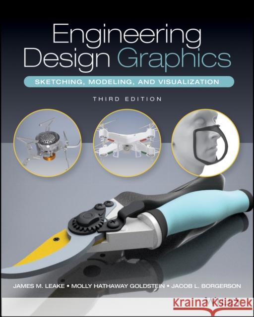
Engineering Design Graphics » książka


Engineering Design Graphics
ISBN-13: 9781119490432 / Angielski / Miękka / 2022 / 464 str.
Engineering Design Graphics
ISBN-13: 9781119490432 / Angielski / Miękka / 2022 / 464 str.
(netto: 397,46 VAT: 5%)
Najniższa cena z 30 dni: 411,39
ok. 30 dni roboczych.
Darmowa dostawa!
1 ENGINEERING DESIGN 1INTRODUCTION 1ASPECTS OF ENGINEERING DESIGN 1ANALYSIS AND DESIGN 4PRODUCT ANATOMY 5DESIGN PHASES 5DESIGN PROCESS OVERVIEW 6NEEDS ASSESSMENT 7PROBLEM DEFINITION 7BACKGROUND RESEARCH 7DESIGN CRITERIA 8DESIGN CONSTRAINTS 8ALTERNATIVE SOLUTIONS 9ANALYSIS 12EVALUATION AND SELECTION 12SPECIFICATION 16COMMUNICATION 20Written Reports 20Recommended report-writing steps 20Oral Presentations 21BEGINNING VERSUS INFORMED DESIGNER PATTERNS (SIDEBAR) 23CONCURRENT ENGINEERING 23Design for Manufacture and Assembly 25TEAMWORK 26QUESTIONS 272 HUMAN-CENTERED DESIGN AND DESIGN THINKING 29INTRODUCTION 29ENGINEERING DESIGN, ART, AND SCIENCEIntroductionDesign: a fundamental human activityEngineering Design from 1400 to 1900Engineering Education after 1900TWO DESIGN PARADIGMSDesign as rational problem solvingDesign as a reflective practiceWICKED PROBLEMSDIVERGENT AND CONVERGENT QUESTIONINGDOUBLE DIAMOND DESIGN PROCESSHUMAN-CENTERED DESIGNDESIGN THINKINGIntroductionThree spaces of innovationInspirationObservationEmpathyIdeationEmpathyIdeationBrainstormingPrototypingImplementationTest and iterateT-shaped individuals (sidebar)Radical collaborationQUESTIONS3 PRODUCT DISSECTIONINTRODUCTIONPRODUCT SUITABILITYPRODUCT DISSECTION PROCEDUREPRE-DISSECTION ANALYSISDISSECTIONCraftsman locking pliers disassembly stepsPRODUCT DOCUMENTATIONPRODUCT ANALYSISPRODUCT IMPROVEMENTREASSEMBLYCOMMUNICATIONQUESTIONS4 FREEHAND SKETCHINGINTRODUCTIONSKETCHING TOOLS AND MATERIALSSKETCHING TECHNIQUESLine TechniquesSketching Straight LinesSketching CirclesSketching EllipsesPROPORTIONINGEstimating Dimensions of Actual ObjectsPartitioning LinesINSTRUMENT USAGE--TRIANGLESParallel LinesPerpendicular LinesLINE STYLESQUESTIONS5 PLANAR PROJECTIONS AND PICTORIAL VIEWSPLANAR PROJECTIONSIntroductionClassification of Planar Projections: Projector CharacteristicsPreliminary DefinitionsBlock coefficientClassification of Planar Projections: Orientation of Object with Respect to Projection PlaneFurther Distinctions Between Parallel and Perspective ProjectionsClasses of Parallel ProjectionsOBLIQUE PROJECTIONSOblique Projection GeometryOblique Projection AngleClasses of Oblique ProjectionsOblique projection angle in 2DReceding Axis AngleORTHOGRAPHIC PROJECTIONSOrthographic Projection GeometryOrthographic Projection CategoriesAXONOMETRIC PROJECTIONSISOMETRIC PROJECTIONSIsometric DrawingsMultiview ProjectionsINTRODUCTION TO PICTORIAL SKETCHINGOBLIQUE SKETCHESIntroductionAxis OrientationReceding Axis ScaleObject Orientation GuidelinesSketching procedure for a simple extruded shape (see Figure 5-37)Step-by-step cabinet oblique sketch example for a cut block (see Figure 5-38)Step-by-step cavalier oblique sketch example for an object with circular features (see Figure 5-39)ISOMETRIC SKETCHESIntroductionAxis OrientationIsometric ScalingIsometric Grid PaperObject Orientation GuidelinesStep-by-step isometric sketch example for a cut block (see Figure 5-46)Circular Features in an Isometric ViewStep-by-step isometric sketch example for a cylinder (see Figure 5-47)Step-by-step isometric sketch example for a box with holes on three faces (see Figure 5-48)Step-by-step sketch example for an object with circular features (see Figure 5-49)Chapter review: pictorial sketching scalabilityQUESTIONS6 PERSPECTIVE PROJECTIONS AND PERSPECTIVE SKETCHESPERSPECTIVE PROJECTIONHistorical DevelopmentPerspective Projection CharacteristicsClasses of Perspective ProjectionVanishing PointsOne-Point Perspective ProjectionTwo-Point Perspective ProjectionThree-Point Perspective ProjectionPerspective Projection VariablesPerspective projection using a 3D CAD systemProjection plane locationLateral movement of CPVertical movement of CPVarying distance from CPPERSPECTIVE SKETCHESIntroductionTerminologyOne-Point Perspective SketchesTwo-Point Perspective SketchesProportioning TechniquesStep-by-step one-point perspective sketch example (see Figure 6-26)Step-by-step two-point perspective sketch example (see Figure 6-27)Summary: orientation of pictorial sketching axes (see Figure 6-28)QUESTIONS7 MULTIVIEWSMULTIVIEW SKETCHINGIntroduction--Justification and Some CharacteristicsGlass Box TheoryAlignment of ViewsTransfer of DepthView SelectionThird-Angle and First-Angle ProjectionLine ConventionsMultiview drawing of a cylinder (see Figure 7-21)Line PrecedenceGeneric three multiview sketch procedure (see Figure 7-24)Step-by-step multiview sketch example (see Figure 7-25)Intersections and Tangency 92 Fillets and RoundsMachined HolesConventional Representations: Rotated FeaturesStep-by-step multiview sketch example: object with complex features (see Figure 7-33)VISUALIZATION TECHNIQUES FOR MULTIVIEW DRAWINGSIntroduction and MotivationTreatment of Common SurfacesNormal surfacesInclined surfacesOblique surfacesProjection StudiesAdjacent AreasSurface LabelingSimilar ShapesVertex LabelingAnalysis by FeatureMissing-Line and Missing-View ProblemsQUESTIONS8 SECTION AND AUXILIARY VIEWSSECTION VIEWSIntroductionSection View ProcessSection Lining (Hatch Patterns)Full SectionsHalf SectionsOffset SectionsBroken-Out SectionsRevolved SectionsRemoved SectionsConventional Representations: Section ViewsConventional Representations: Thin FeaturesSection View Construction Process--Example 1Section View Construction Process--Example 2Conventional Representations: Aligned SectionsAssembly Section ViewsAUXILIARY VIEWSIntroductionDefinitionsAuxiliary View Projection TheoryAuxiliary Views: Three CasesGeneral Sketching Procedure for Finding a Primary Auxiliary ViewStep 1Step 2Step 3Step 4 (optional)Step 5Step 6Finding a Primary Auxiliary View of a Contoured SurfaceFinding a Partial Auxiliary View, an Isometric Pictorial, and a Missing View, Given Two ViewsQUESTIONS9 DIMENSIONING AND TOLERANCINGDIMENSIONINGIntroductionUnits of MeasurementApplication of DimensionsTerminologyReading direction for dimensional valuesArrangement, placement, and spacing of dimensionsUsing Dimensions to Specify Size and Locate FeaturesSymbols, Abbreviations, and General NotesDimensioning Rules and GuidelinesPrismsCylinders and arcsFinish MarksTOLERANCINGIntroductionDefinitionsTolerance DeclarationTolerance AccumulationMated PartsBasic Hole System: English UnitsBasic Shaft System: English UnitsStep-by-step tolerance calculation of a clearance fit using the basic hole system (see Figure 9-27)Step-by-step tolerance calculation of an interference fit using the basic hole system (see Figure 9-28)Preferred English Limits and FitsRunning or sliding clearance fit (RC)Locational clearance fit (LC)Transition clearance or interference fit (LT)Step-by-step tolerance calculation of a clearance fit using the basic shaft system (see Figure 9-30)Locational interference fit (LN)Force or shrink fit (FN)Step-by-step tolerance calculation using English-unit fit tables, basic hole system (see Figure 9-31)Step-by-step tolerance calculation using English-unit fit tables, basic shaft (see Figure 9-32)Preferred Metric Limits and FitsStep-by-step tolerance calculation using metric-unit fit tables, hole basis (see Figure 9-39)Step-by-step tolerance calculation using metric-unit fit tables, shaft basis (see Figure 9-40)Tolerancing in CADQUESTIONS10 CAD: SOLID MODELINGINTRODUCTIONComputer-Aided DesignCategories of CAD SystemsComputer-aided drawingSolid modelingTopology (Sidebar)Parametric modelingDirect modelingSurface Modeling - NURBS and FreeformBuilding Information Modeling (BIM) (Sidebar)CAD Viewing and DisplayPARAMETRIC MODELINGIntroductionTerminologyPart ModelingIntroductionSketch modeFeature creationPart editingPart creation process (see Figure 10-32)Assembly ModelingIntroductionJointsCAD librariesAdvanced Modeling StrategiesCloud-Based CADQUESTIONS 24111 CAD: NURBS AND FREEFORM SURFACE MODELINGNURBS SURFACE MODELINGIntroductionParametric Curves and Cubic SplinesParametric representation of a curve (sidebar)Bézier CurvesB-SplinesNURBSSurfacesCurvatureContinuityClass A SurfacesFREEFORM SURFACE MODELINGIntroductionPolygon meshes and polygonal modelingSubdivision surfacesNURBS LimitationsT-SplinesThe Bézier Award (Sidebar)QUESTIONS12 PRODUCT DOCUMENTATIONWORKING DRAWINGSModel-based definitionDETAIL DRAWINGSASSEMBLY DRAWING VIEWSBILL OF MATERIALS AND BALLOONSSHEET SIZESTITLE BLOCKSBORDERS AND ZONESREVISION BLOCKSDRAWING SCALETOLERANCE NOTESSTANDARD PARTSWORKING DRAWING CREATION USING PARAMETRIC MODELING SOFTWAREExtracting a detail drawing from a parametric part model (see Figure 12-16)Using existing part models to create an assembly model (see Figure 12-17)Extracting a sectioned assembly drawing (see Figure 12-18)Creating an exploded view (see Figure 12-19)Creating an exploded view drawing with parts list and balloons (see Figure 12-20)INDUSTRY SPOTLIGHT: FISKARS GROUPQUESTIONS13 ADDITIVE MANUFACTURINGINTRODUCTIONAM TECHNOLOGIESVat photopolymerizationMaterial extrusionPowder bed fusionMaterial jettingCLASSIFICATION OF AM TECHNOLOGIES3D PRINTER FILE FORMATSSTL REPAIR TOOLSCHARACTERISTICS OF AM SYSTEMSPart orientationSupport structureHatch styleLOW-COST AMIndustrial category AMProfessional category 3D printersConsumer (home and hobby, desktop) category 3D printersDESIGN FOR ADDITIVE MANUFACTURINGDesign for conventional manufacturing processesDesign for AMQUESTIONS9 3D SCANNINGREVERSE ENGINEERING3D SCANNINGIntroduction3D Scanner PipelineMesh terminology3D Scanning TechnologiesContact-based scannersNoncontact scannersLaser triangulationStructured LightReality CapturePhotogrammetryTime of FlightReverse Engineering SoftwareMesh reconstruction (or point processing)NURBS surface modeling from scan dataParametric CAD model from scan dataQUESTIONS15 SIMULATIONUPFRONT ANALYSISFINITE ELEMENT ANALYSISModeling and MeshingBoundary ConditionsContour plotResultsFEA workflowGENERATIVE DESIGNGenerative design workflowDYNAMICS SIMULATION SOFTWAREDynamics Simulation Software DemonstrationQUESTIONSA ANSI PREFERRED ENGLISH LIMITS AND FITSB ANSI PREFERRED METRIC LIMITS AND FITSINDEX 3DRAWING SHEETS
1997-2026 DolnySlask.com Agencja Internetowa
KrainaKsiazek.PL - Księgarnia Internetowa


