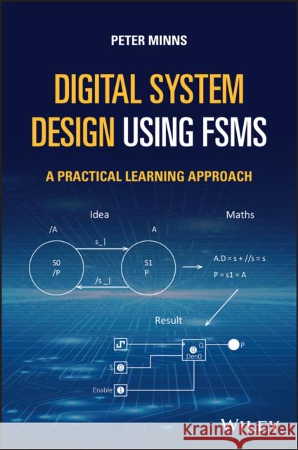
Preface viiiAcknowledgements xAbout the Companion Website xiGuide to Supplementary Resources xii1 Introduction to Finite State Machines 11.1 Some Notes on Style 12 Using FSMs to Control External Devices 252.1 Introduction 253 Introduction to FSM Synthesis 453.1 Introduction 453.2 Tutorials Covering Chapters 1, 2, and 3 713.2.1 Binary data serial transmitter FSM 713.2.2 The high low FSM system 763.2.3 The clocked watchdog timer FSM 803.2.3.1 FSM equations 813.2.4 The asynchronous receiver system clocked FSM 843.2.4.1 Brief note on the development of the test bench generator 863.2.4.2 The state diagram 863.2.4.3 The state diagram equations 873.2.4.4 The outputs 873.2.4.5 Verilog HDL simulation of the completed system 954 Asynchronous FSM Methods 974.1 Introduction to Asynchronous FSM 974.2 Summary 1444.3 Tutorials 1444.3.1 FSM motor with fault detection 1444.3.2 The mower in four and two states 1485 Clocked One Hot Method of FSM Design 1535.1 Introduction 1535.2 Tutorials on the Clocked One Hot FSM Method 1685.2.1 Seven-state system clocked one hot method 1685.2.2 Memory tester FSM 1705.2.3 Eight-bit sequence detector FSM 1746 Further Event-Driven FSM Design 1796.1 Introduction 1796.2 Conclusions 1957 Petri Net FSM Design 1977.1 Introduction 1977.2 Tutorials Using Petri Net FSM 2347.2.1 Controlled shared resource Petri nets 2347.2.2 Serial clock-driven Petri net FSM 2407.2.3 Using asynchronous (event-driven) design with Petri nets 2477.3 Conclusions 249Appendix A1: Boolean Algebra 251A1.1 Basic Gate Symbols 251A1.2 The Exclusive OR and Exclusive NOR 252A1.3 Laws of Boolean Algebra 252A1.3.1 Basic OR rules 252A1.3.2 Basic AND rules 253A1.3.3 Associative and commutative laws 253A1.3.4 Distributive laws 253A1.3.5 Auxiliary rule for static 1 hazard removal 254A1.3.5.1 Proof of the Auxiliary Rule 254A1.3.6 Consensus theorem 254A1.3.7 The effect of signal delay in logic gates 255A1.3.8 De-Morgan's theorem 256A1.4 Examples of Applying the Laws of Boolean Algebra 257A1.4.1 Converting AND-OR to NAND 257A1.4.2 Converting AND-OR to NOR 257A1.4.3 Logical adjacency rule 258A1.5 Summary 258Appendix A2: Use of Verilog HDL and Logisim to FSM 261A2.1 The Single-Pulse Generator with Memory Clock-Driven FSM 261A2.2 Test Bench Module and its Purpose 267A2.3 Using Synapticad Software 268A2.4 More Direct Method 270A2.5 A Very Simple Guide to Using the Logisim Simulator 271A2.5.1 The Logisim top level menu items 271A2.6 Using Flip-Flops in a Circuit 273A2.7 Example Single-Pulse FSM 275A2.8 How to Use the Simulator to Simulate the Single-Pulse FSM 278A2.8.1 Using Logisim with the truth table approach 278A2.9 Using Logisim with the Truth Table Approach 279A2.9.1 Useful note 281A2.10 Summary 281Appendix A3: Counters, Shift Registers, Input, and Output with an FSM 285A3.1 Basic Down Synchronous Binary Counter Development 285A3.2 Example of a Four-Bit Synchronous Up Counter with T Type Flip-Flops 288A3.3 Parallel Loading Counters - Using T Flip-Flops 291A3.4 Using D Flip-Flops To Build Parallel Loading Counters 292A3.5 Simple Binary Up Counter with Parallel Inputs 293A3.6 Clock Circuit to Drive the Counter (and FSM) 294A3.7 Counter Design Using Don't Care States 295A3.8 Shift Registers 296A3.9 Dealing with Input and Output Signals Using FSM 298A3.10 Using Logisim to Work with Larger FSM Systems 301A3.10.1 The equations 302A3.11 Summary 305Appendix A4: Finite State Machines Using Verilog Behavioural Mode 307A4.1 Introduction 307A4.2 The Single-Pulse/Multiple-Pulse Generator with Memory FSM 307A4.3 The Memory Tester FSM Revisited 313A4.4 Summary 315Appendix A5: Programming a Finite State Machine 317A5.1 Introduction 317A5.2 The Parallel Loading Counter 317A5.3 The Multiplexer 319A5.4 The Micro Instruction 320A5.5 The Memory 320A5.6 The Instruction Set 321A5.7 Simple Example: Single-Pulse FSM 323A5.8 The Final Example 325A5.9 The Program Code 328A5.10 Returning Unused States via Other Transition Paths 328A5.11 Summary 328Appendix A6: The Rotational Detector Using Logisim Simulator with Sub-Circuits 329A6.1 Using the Two-State Diagram Arrangement 333Bibliography 335Index 337
Peter D. Minns, PhD, now retired, has over 33 years experience as an academic Senior Lecturer, most recently in the Department of Mathematics, Physics, and Electrical Engineering at Northumbria University at Newcastle, UK. Prior to academia, he worked in the telecommunications industry and in Power System Protection as a Design and Development Engineer.