Approaches for Clean Combustion in Gas Turbines » książka


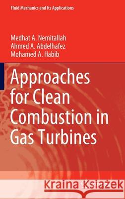
Approaches for Clean Combustion in Gas Turbines
ISBN-13: 9783030440763 / Angielski / Twarda / 2020 / 417 str.
Approaches for Clean Combustion in Gas Turbines
ISBN-13: 9783030440763 / Angielski / Twarda / 2020 / 417 str.
(netto: 613,40 VAT: 5%)
Najniższa cena z 30 dni: 616,85
ok. 16-18 dni roboczych.
Darmowa dostawa!
Chapter 1: Introduction
1.1 Introduction
1.2 Global warming issue
1.3 Status of renewables
1.4 Carbon capture technologies
1.5 Adaptation of gas turbines to regulations of pollutant emissions
1.6 Emission regulatory overview
1.6.1 Clean air act (CAA)
1.6.2 New source performance standards (NSPS)
1.6.3 New source review
1.6.4 Best available control technology (BACT)
1.6.5 Lowest achievable emission rate (LAER)
1.7 Clean power production for gas turbine applications
1.8 Concluding remarks
Chapter 2: Premixed combustion for gas turbine applications
2.1 Introduction
2.2 Combustor Operability Issues
2.2.1 Static instabilities
2.2.1.1 Blowout
2.2.1.2 Flashback
2.2.2 Dynamic instabilities
2.2.2.1 Thermo-acoustics
2.2.2.2 Dynamic Instability suppression methods
2.3 Approaches for efficient combustion
2.3.1 Fuel flexibility Approach
2.3.1.1 Oxy-fuel combustion approach
2.3.1.1.1 Oxy-combustion degrees of freedom
2.3.1.1.2 Effect of oxy-combustion on stability map
2.3.1.1.3 Effect of oxy-combustion on NO emissions
2.3.1.2 Hydrogen-enrichment approach
2.3.1.2.1 Effect of hydrogen enrichment on stability map
2.3.1.2.2 Effect of hydrogen on laminar burning velocity
2.3.1.2.3 Effect of Hydrogen on NOx and CO emissions
2.3.2 Variable operating conditions approach
2.3.3 Variable flame characteristics
2.3.3.1 Diffusion flame
2.3.3.2 Premixed flames
2.4 Swirl Stabilizer Approach for stability and emission enhancement
2.4.1 Stabilization mechanisms and swirl number
2.4.2 Effect of swirl number on flame stability
2.4.3 Effect of swirl on NOx and CO emissions
2.5 Numerical modeling of premixed combustion
2.5.1 Turbulent premixed combustion
2.5.2 Turbulent combustion modeling schemes
2.5.3 LES governing equations
2.5.4 LES for turbulent premixed combustion
2.6 Premixed combustion in a gas turbine model combustor: Numerical case study
2.6.1 Model validation
2.6.2 Premixed Oxy-combustion case study
2.6.3 Results and discussion of the present case study
2.7 Concluding remarks
Chapter 3: Burner designs for clean power generation in gas turbines
3.1 Introduction
3.2 Lean premixed air combustion
3.2.1 Combustion and emissions characteristics
3.2.2 Combustion instabilities and solution techniques
3.3 Oxy-combustion for carbon capture
3.3.1 Oxy-fuel combustion technology
3.3.2 Comparison of air vs oxy-combustion concepts
3.4 Premixed oxy-fuel combustion
3.4.1 Characteristics of premixed oxy-combustion
3.4.2 Emission characteristics of premixed oxy-combustion
3.5 Fuel-flexible combustion approach
3.5.1 Fuel flexibility
3.5.2 Fuel-flexible combustion approaches
5.3.2.1 Hydrogen enrichment
5.3.2.2 Syngas combustion
5.3.2.3 Ammonia combustion
3.5.3 Fuel-flexible premixed oxy-fuel combustion
3.6 Gas turbine combustion systems
3.6.1 Stagnation point reverse flow (SPRF) burners
3.6.2 Dry low-NOx/low-emissions (DLN/DLE) burners
3.6.3 EnVironmental (EV/AEV/SEV) burners
3.6.4 Micromixer (MM) combustion technology
3.6.4.1 Perforated plate burners
3.6.4.2 Micromixer combustion technology
3.6.4.2.1 Fuel/oxidizer-flexible combustion in micromixer burners
3.6.4.2.2 Hydrogen-rich combustion in micromixers
3.7 High-temperature membrane reactors (HTMRs)
3.8 International trends in CCS/CCUS technologies
3.9 Concluding remarks
Chapter 4: Gas turbine performance for different burner technologies
4.1 Introduction
4.2 Dry low-NOx/low-emissions (DLN/DLE) burners for gas turbines
4.3 Combustor operability of premixed oxy-methane flames
4.3.1 Test conditions
4.3.2 Combustor Stability Maps
4.3.3 Flame macrostructure
4.3.4 Flame temperature
4.3.5 LES of premixed oxy-flames
4.3.5.1 Model setup
4.3.5.2 Model validation
4.3.5.3 Flow and flame characteristics
4.4 Oxy-methane vs oxygen-enriched-air flames for gas turbine applications
4.4.1 Air flames vs oxy-flames
4.4.2 Role of adiabatic flame temperature for controlling flame stabilization
4.4.3 Role of adiabatic flame temperature for controlling flame structure
4.5 Role of flow Reynolds for controlling flame structure and stabilization
4.5.1 Effect of inlet flow conditions on flame stability
4.5.2 Role of flow Reynolds for controlling flame stabilization
4.5.3 Role of flow Reynolds for controlling flame structure
4.6 Micromixer burners for gas turbines
4.7 Operability of micromixer combustor holding premixed oxy-methane flames
4.7.1 Combustor design
4.7.2 Combustor stability maps
4.7.3 Flame temperature
4.8 Performance of solar-integrated oxy-combustion cycles adopting membrane reactors
4.8.1 Oxygen separation techniques for oxy-combustion cycles
4.8.2 Proposed power generation cycles
4.8.3 Performance of the proposed cycles
4.8.4 Modified power generation cycles
4.8.5 Performance of the modified cycles
Chapter 5: Operability of fuel/oxidizer-flexible gas turbine combustors
5.1 Oxidizer flexibility in gas turbines
5.1.1 Oxy-combustion flames
5.1.2 Oxidizer Dilution
5.2 Fuel flexibility in gas turbines
5.3 Combined fuel and oxidizer flexible flames
5.4 Combustor operability of H2-enriched premixed oxy-methane flames
5.4.1 Operating conditions
5.4.2 Combustor stability maps
5.4.3 Effect of inlet velocity on flame stability
5.4.4 Operability of oxy-methane vs H2-eneriched oxy-methane flames
5.4.5 Mechanisms of flashback and blowout
5.4.6 Modeling H2-enriched oxy-methane flames
5.4.6.1 LES model setup
5.4.6.2 Model validation
5.4.6.3 Flow field characteristics
5.4.6.4 Flame characteristics
5.5 Combustor operability under stoichiometric H2-enriched conditions
5.5.1 Flame stability mapping
5.5.2 Effect of inlet velocity on flame stability
5.6 Combustor operability of premixed oxy-propane flames
5.6.1 Test conditions
5.6.2 Stability maps of oxy-propane flames
5.6.3 Operability of oxy-methane vs oxy-propane flames
5.6.4 Flame macrostructure5.6.5 Characterization of flame temperature
Chapter 6: Porous-plates and hybrid membrane reactors for gas turbine applications
6.1 Concept of membrane separation
6.1.1 Ceramic membranes
6.1.2 Polymeric membranes
6.2 Polymeric membranes for oxygen-enriched air combustion applications
6.2.1 Description of membrane unit and ranges of parameters
6.2.2 CFD modeling
6.2.3 Effect of sweep gas flow rate
6.2.4 Effect of feed gas flow rate
6.2.5 Effect of feed pressure
6.2.6 Effect of polymer material
6.2.7 Multi-stage separation
6.3 Ceramic membrane reactors for oxy-fuel combustion applications
6.4 Hybrid polymeric-ceramic membrane reactor for gas turbine applications
6.4.1 Design of polymeric membrane unit
6.4.2 Design of oxygen transport membrane reactor (OTMR) unit
6.4.3 Analysis of the hybrid unit
6.4.4 Effect of feed O2 mass fraction
6.4.5 Effect of swept fuel mass fraction
6.4.6 Effect of feed flow rate
6.4.7 Effect of sweep flow rate
6.4.8 Design and energy analysis of the hybrid unit
6.5 Low-power porous-plate reactors
6.5.1 Combustion characteristics in porous-plate reactors
6.5.2 Operating conditions
6.5.3 Modeling non-reactive flow in porous-plate reactor
6.5.4 Modeling reactive flow in porous-plate reactor
6.5.5 Non-reactive flow field characteristics
6.5.6 Reactive flow field characteristics
6.6 Operability limits of porous-plate reactor mimicking OTMR operation
6.6.1 Combustor setup
6.6.2 Flame shape
6.6.3 Combustion temperature
6.6.4 Lean blowout limits
6.7 Practice engineering problems
6.8 Concluding remarksChapter 1: Introduction
1.1 Introduction
1.2 Global warming issue
1.3 Status of renewables
1.4 Carbon capture technologies
1.5 Adaptation of gas turbines to regulations of pollutant emissions
1.6 Emission regulatory overview
1.6.1 Clean air act (CAA)
1.6.2 New source performance standards (NSPS)
1.6.3 New source review
1.6.4 Best available control technology (BACT)
1.6.5 Lowest achievable emission rate (LAER)
1.7 Clean power production for gas turbine applications
1.8 Concluding remarks
Chapter 2: Premixed combustion for gas turbine applications
2.1 Introduction
2.2 Combustor Operability Issues
2.2.1 Static instabilities
2.2.1.1 Blowout
2.2.1.2 Flashback
2.2.2 Dynamic instabilities
2.2.2.1 Thermo-acoustics
2.2.2.2 Dynamic Instability suppression methods
2.3 Approaches for efficient combustion
2.3.1 Fuel flexibility Approach
2.3.1.1 Oxy-fuel combustion approach
2.3.1.1.1 Oxy-combustion degrees of freedom
2.3.1.1.2 Effect of oxy-combustion on stability map
2.3.1.1.3 Effect of oxy-combustion on NO emissions
2.3.1.2 Hydrogen-enrichment approach
2.3.1.2.1 Effect of hydrogen enrichment on stability map
2.3.1.2.2 Effect of hydrogen on laminar burning velocity
2.3.1.2.3 Effect of Hydrogen on NOx and CO emissions
2.3.2 Variable operating conditions approach
2.3.3 Variable flame characteristics
2.3.3.1 Diffusion flame
2.3.3.2 Premixed flames
2.4 Swirl Stabilizer Approach for stability and emission enhancement
2.4.1 Stabilization mechanisms and swirl number
2.4.2 Effect of swirl number on flame stability
2.4.3 Effect of swirl on NOx and CO emissions
2.5 Numerical modeling of premixed combustion
2.5.1 Turbulent premixed combustion
2.5.2 Turbulent combustion modeling schemes
2.5.3 LES governing equations
2.5.4 LES for turbulent premixed combustion
2.6 Premixed combustion in a gas turbine model combustor: Numerical case study
2.6.1 Model validation
2.6.2 Premixed Oxy-combustion case study
2.6.3 Results and discussion of the present case study
2.7 Concluding remarks
Chapter 3: Burner designs for clean power generation in gas turbines
3.1 Introduction
3.2 Lean premixed air combustion
3.2.1 Combustion and emissions characteristics
3.2.2 Combustion instabilities and solution techniques
3.3 Oxy-combustion for carbon capture
3.3.1 Oxy-fuel combustion technology
3.3.2 Comparison of air vs oxy-combustion concepts
3.4 Premixed oxy-fuel combustion
3.4.1 Characteristics of premixed oxy-combustion
3.4.2 Emission characteristics of premixed oxy-combustion
3.5 Fuel-flexible combustion approach
3.5.1 Fuel flexibility
3.5.2 Fuel-flexible combustion approaches
5.3.2.1 Hydrogen enrichment
5.3.2.2 Syngas combustion
5.3.2.3 Ammonia combustion
3.5.3 Fuel-flexible premixed oxy-fuel combustion
3.6 Gas turbine combustion systems
3.6.1 Stagnation point reverse flow (SPRF) burners
3.6.2 Dry low-NOx/low-emissions (DLN/DLE) burners
3.6.3 EnVironmental (EV/AEV/SEV) burners
3.6.4 Micromixer (MM) combustion technology
3.6.4.1 Perforated plate burners
3.6.4.2 Micromixer combustion technology
3.6.4.2.1 Fuel/oxidizer-flexible combustion in micromixer burners
3.6.4.2.2 Hydrogen-rich combustion in micromixers
3.7 High-temperature membrane reactors (HTMRs)
3.8 International trends in CCS/CCUS technologies
3.9 Concluding remarks
Chapter 4: Gas turbine performance for different burner technologies
4.1 Introduction
4.2 Dry low-NOx/low-emissions (DLN/DLE) burners for gas turbines
4.3 Combustor operability of premixed oxy-methane flames
4.3.1 Test conditions
4.3.2 Combustor Stability Maps
4.3.3 Flame macrostructure
4.3.4 Flame temperature
4.3.5 LES of premixed oxy-flames
4.3.5.1 Model setup
4.3.5.2 Model validation
4.3.5.3 Flow and flame characteristics
4.4 Oxy-methane vs oxygen-enriched-air flames for gas turbine applications
4.4.1 Air flames vs oxy-flames
4.4.2 Role of adiabatic flame temperature for controlling flame stabilization
4.4.3 Role of adiabatic flame temperature for controlling flame structure
4.5 Role of flow Reynolds for controlling flame structure and stabilization
4.5.1 Effect of inlet flow conditions on flame stability
4.5.2 Role of flow Reynolds for controlling flame stabilization
4.5.3 Role of flow Reynolds for controlling flame structure
4.6 Micromixer burners for gas turbines
4.7 Operability of micromixer combustor holding premixed oxy-methane flames
4.7.1 Combustor design
4.7.2 Combustor stability maps
4.7.3 Flame temperature
4.8 Performance of solar-integrated oxy-combustion cycles adopting membrane reactors
4.8.1 Oxygen separation techniques for oxy-combustion cycles
4.8.2 Proposed power generation cycles
4.8.3 Performance of the proposed cycles
4.8.4 Modified power generation cycles
4.8.5 Performance of the modified cycles
Chapter 5: Operability of fuel/oxidizer-flexible gas turbine combustors
5.1 Oxidizer flexibility in gas turbines
5.1.1 Oxy-combustion flames
5.1.2 Oxidizer Dilution
5.2 Fuel flexibility in gas turbines
5.3 Combined fuel and oxidizer flexible flames
5.4 Combustor operability of H2-enriched premixed oxy-methane flames
5.4.1 Operating conditions
5.4.2 Combustor stability maps
5.4.3 Effect of inlet velocity on flame stability
5.4.4 Operability of oxy-methane vs H2-eneriched oxy-methane flames
5.4.5 Mechanisms of flashback and blowout
5.4.6 Modeling H2-enriched oxy-methane flames
5.4.6.1 LES model setup
5.4.6.2 Model validation
5.4.6.3 Flow field characteristics
5.4.6.4 Flame characteristics
5.5 Combustor operability under stoichiometric H2-enriched conditions
5.5.1 Flame stability mapping
5.5.2 Effect of inlet velocity on flame stability
5.6 Combustor operability of premixed oxy-propane flames
5.6.1 Test conditions
5.6.2 Stability maps of oxy-propane flames
5.6.3 Operability of oxy-methane vs oxy-propane flames
5.6.4 Flame macrostructure5.6.5 Characterization of flame temperature
Chapter 6: Porous-plates and hybrid membrane reactors for gas turbine applications
6.1 Concept of membrane separation
6.1.1 Ceramic membranes
6.1.2 Polymeric membranes
6.2 Polymeric membranes for oxygen-enriched air combustion applications
6.2.1 Description of membrane unit and ranges of parameters
6.2.2 CFD modeling
6.2.3 Effect of sweep gas flow rate
6.2.4 Effect of feed gas flow rate
6.2.5 Effect of feed pressure
6.2.6 Effect of polymer material
6.2.7 Multi-stage separation
6.3 Ceramic membrane reactors for oxy-fuel combustion applications
6.4 Hybrid polymeric-ceramic membrane reactor for gas turbine applications
6.4.1 Design of polymeric membrane unit
6.4.2 Design of oxygen transport membrane reactor (OTMR) unit
6.4.3 Analysis of the hybrid unit
6.4.4 Effect of feed O2 mass fraction
6.4.5 Effect of swept fuel mass fraction
6.4.6 Effect of feed flow rate
6.4.7 Effect of sweep flow rate
6.4.8 Design and energy analysis of the hybrid unit
6.5 Low-power porous-plate reactors
6.5.1 Combustion characteristics in porous-plate reactors
6.5.2 Operating conditions
6.5.3 Modeling non-reactive flow in porous-plate reactor
6.5.4 Modeling reactive flow in porous-plate reactor
6.5.5 Non-reactive flow field characteristics
6.5.6 Reactive flow field characteristics
6.6 Operability limits of porous-plate reactor mimicking OTMR operation
6.6.1 Combustor setup
6.6.2 Flame shape
6.6.3 Combustion temperature
6.6.4 Lean blowout limits
6.7 Practice engineering problems
6.8 Concluding remarks
This book focuses on the development of novel combustion approaches and burner designs for clean power generation in gas turbines. It shows the reader how to control the release of pollutants to the environment in an effort to reduce global warming. After an introduction to global warming issues and clean power production for gas turbine applications, subsequent chapters address premixed combustion, burner designs for clean power generation, gas turbine performance, and insights on gas turbine operability. Given its scope, the book can be used as a textbook for graduate-level courses on clean combustion, or as a reference book to accompany compact courses for mechanical engineers and young researchers around the world.
1997-2026 DolnySlask.com Agencja Internetowa
KrainaKsiazek.PL - Księgarnia Internetowa


